
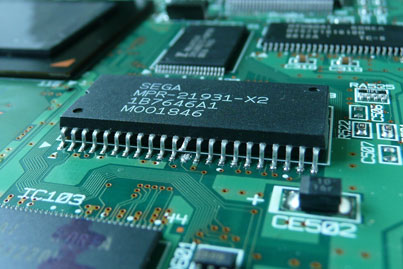
Dreamcast Dev Bios (Region Free Too!)
![]()
UPDATE
Looking for a cheap reliable source for this
chip, I've bought some from
Bad_Ad84
via assemblergames, he even offers a flashing service :-) If you buy a
pre-flashed chip, then you can simply remove the old BIOS and fit the new one,
you still need to lift and solder leg 44 as per the notes below, and lift leg 1
and solder it to 23, and if you've
got an early motherboard then you'll need to pay attention about powering the
chip (legs 1 and 23), as per the notes below. I have put some photo's at
the end of this page.
Link83 did some amazing work and combined the Dreamcast Dev BIOS (different startup screen) with the Retail BIOS and made it truly Region Free.
Have a look at the startup animation which has been hacked into the BIOS, it's from a DC Dev machines and looks great :-)
Why perform this mod? Well you'll end up with a DreamCast which is different to most others, plus it will be truly region free, the current 4 wire modchips need you to switch the console off and back on again if swapping between different region discs. This one skips any region checking at all.
Link83 UPDATE - Extra info about that early VA0 DC
Motherboard:
the VA0 Dreamcast motherboard (Mainly early Japanese and USA consoles) need a 5V
flash chip, and that the VA1 and VA2.1 Dreamcast motherboards use a 3.3V flash
chip. You can tell which motherbaord will be inside your Dreamcast by looking
for a small circled (0) (1) or (2) on the silver sticker on the bottom of the
casing.
DarthCloud has also written some extra info on the subject here.
I have to say a BIG thanks to Link83 for experimenting with the BIOS, DarthCloud on ASSEMblergames for all the detailed info about fitting the chip and the Russian DC-SWAT team for the original DreamShell disc which I modified to make flashing Link83s BIOS easier and also for their original installation diagrams.
Start by lifting leg 12 of the original bios chip, I gently heat the leg where it joins the motherboard and then with a scalpel I lever it up, and carefully straighten it with a pair of pliers.
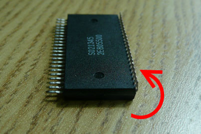
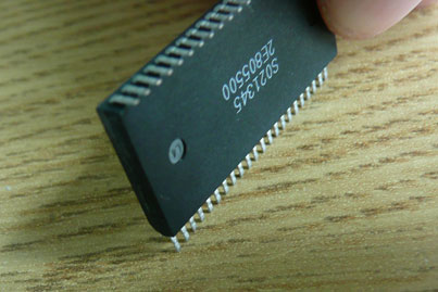
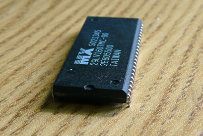
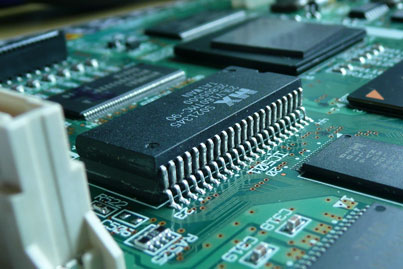
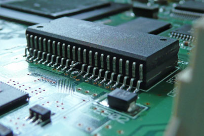
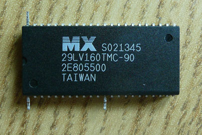
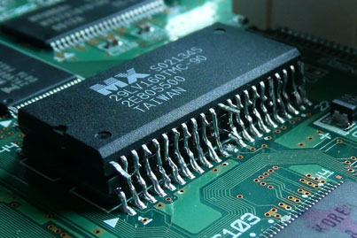
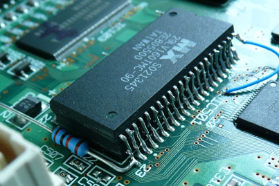
Then start on the Flash Chip 29LV160TMC-90. We need to start with straightening the chip legs
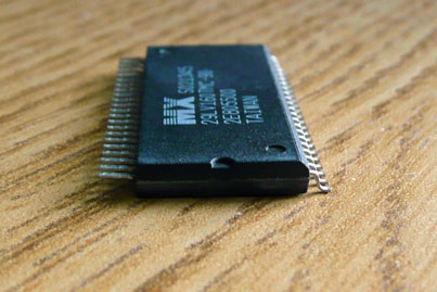
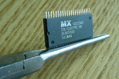
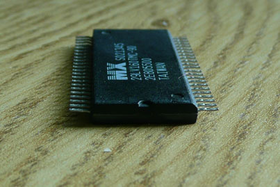
Then we need to bend them again, this time they should just have one bend in them. Hold the chip vertically so all the legs are pressed against a flat surface. Then push the chip so that all legs are bent at a 90 degree angle to the chip, repeat on the other side.
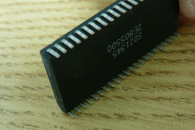
Then test fit the new chip onto the existing chip. The legs will probably be a bit too short, but that's okay, we can still solder them together.
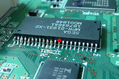
Remove the new chip, and now prepare the existing chip. I was worried about adding too much solder to the BIOS chips legs and joining two or more together. So decided to work my way around with a continuity meter and discovered that legs 32 and 33 are already linked together. When I finished preparing the legs, I did the same check.
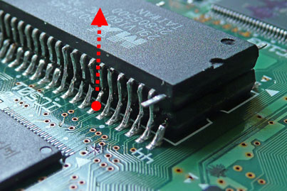
We want to add a small amount of solder onto each leg, once you pickup the technique for this it won't take too long. I hold the tip of my soldering iron on the very top of the leg (on the red dot in the photo), it heats the leg up, be ready to immediately add a small amount of solder to the leg, it should quickly take to the leg and cover it. The photo below shows I've done legs on the left hand side.
You need to now straighten some legs on the new BIOS chip as we don't want these soldered to the old chip legs. Gently bend legs 1, 12 and 44 out flat (also do leg 23 if fitting on a VA0 motherboard).
Now I place the new chip on top of the old one, and dragged the solder up from the old leg onto the new leg. The photo below shows I've done the first few legs on the right of the photo, the red dot is where I place the soldering iron tip, and then drag the iron up onto the new legs, taking some solder with it.
Work your way around and do this to every leg. Don't worry too much if you don't join the legs up first time. The photo below shows a couple of legs that didn't join up, this is easily fixed though.

It could be that the legs on the new flash chip have been bent too much, and you need to pull them out a bit so that they are level with the old chip legs, then try the same technique of dragging the solder from the old leg to the new leg.
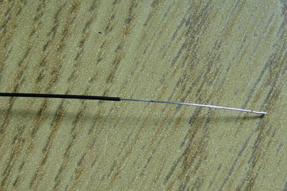
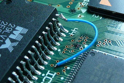
If that doesn't work, then we can add a piece of wire, this is Kynar wire, I've stripped a length of exposing a couple of centimetres of bare wire.
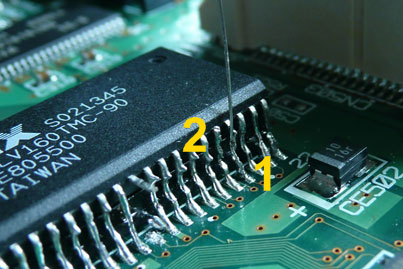
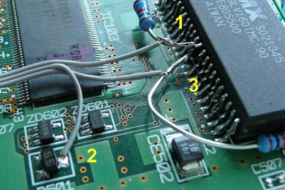
Hold the wire in place, heat up the solder on the old chip leg (Number 1 below), then heat up the solder that you had previously dragged up onto the new chips legs (Number 2), then trim the wire. Repeat this on all the legs.
Now, you can test your soldering again. Check each leg with a continuity tester and make sure that it confirms that the old and new leg are soldered together. If you think you've put too much solder on a leg and joined to adjacent legs, then you could test this also (remember that legs 32 and 33 are already linked up)
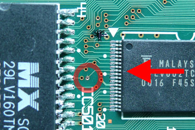
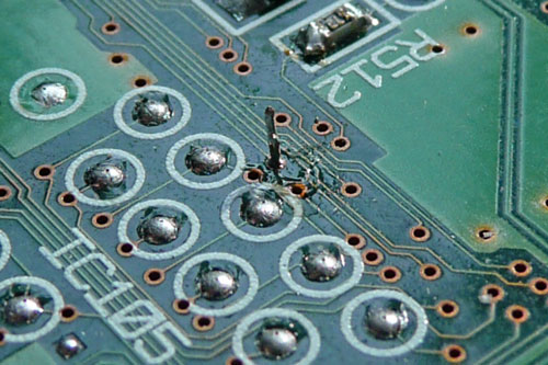
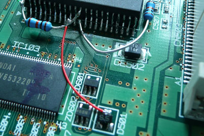
Lets start with the most awkward wire to solder now. The leg of the flash chip needs to be linked to pin 9 of the adjacent chip just behind it (assuming VA1 motherboard, on the VA0 motherboard it's leg 7). Look how small those legs are! You should be able to see that the leg is linked up to a small hole on the motherboard, I gently scraped the coating from that hole (you can see that in the first photo above), and then melted a small bit of solder onto the point.
You can see the short piece of Kynar wire that I've used to link leg 44 to the contact point.
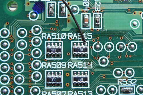
Alternatively, if you're using Kynar wire, you can strip it and push it through the whole and solder it onto the other side. If you still don't fancy that, it's linked up to a leg on RA515 which is on the bottom of the motherboard (these photos are from a VA1 motherboard, it may look different on the VA0)
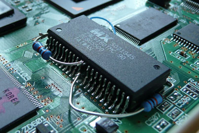
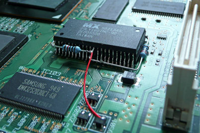
Now grab your 10k resistors, you can see how I've bent and soldered the first one to the joined up legs 23, and the other end of that goes to the lifted leg 12 of the existing BIOS chip. The second resistor was cut and bent to fit between legs 1 and 12 of the new Flash chip.

Once the resistors are in place, solder a final wire inbetween leg 1 of the new chip (there's already a resistor soldered to it remember), to the linked up legs 23 of both legs (opposite corner of chips, also has a resistor coming off of it). That's the green wire in the photo above.
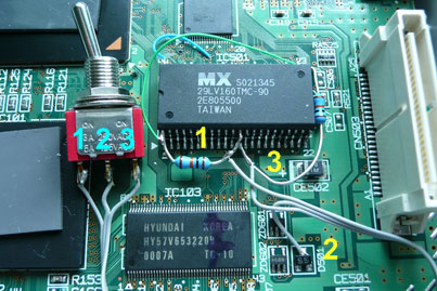
Now it's time to solder the switch in place. I hope the numbered photos above explain what to solder to each leg etc. Middle contact of the switch to the single point of D501 on the motherboard, either side of the switch contacts to the resistors near where they link up to legs 12 of the chips. The switch is used to select which BIOS is loaded when you switch the console on, either the existing one or Link83s modified one.
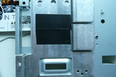
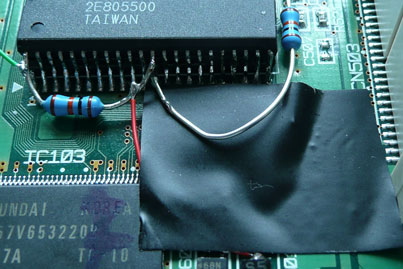
It's ready to re-assemble now. I decided to insulate the metal plate directly above the new BIOS chip just in case one of the resistors move and touches it. You can re-assemble the console but leave all the screws and the top of the case of, you can then use the switch and hold the lid control switch also.
Switch your machine on and if you get a blank screen then you've probably got the switch in the position which selects the new (currently blank) BIOS. Flick the switch and restart the console. It should start up now as expected, set the date and time (that's because you had to remove the controller ports with the battery on.
Download and burn the link83.nrg Nero Burning ROM disc image. I burn it at 4 speed Disk At Once mode. Pop the disc on, hold or tape the lid control switch and either restart the console or select Play from the dashboard. This disc is a customised version of DC-Swat DreamShell disc, I've altered the configuration files and deleted the alternative BIOS files to try and make the download as small as possible.

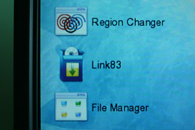
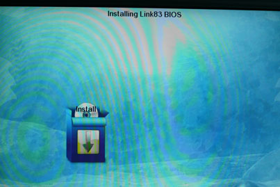
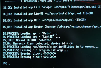
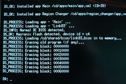
The screenshots above show you what to select, but it's pretty much self explanatory :-) Before selecting Install from the last screenshot, flick the switch you've installed to the other position selecting the new Flash chip. After you select Install, the screen goes black, with white writing, it should display some info about the Flash chip you've just installed, pause for around 15 or so seconds, and then start erasing the chip, then immediately start writing to it.
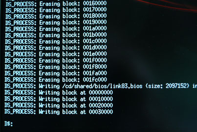
You shouldn't get any errors during the erase or writing stage. I did the first time I did this, and that was because I didn't link up legs 23 properly on the BIOS chips. The flashing software correctly identified the chip, but couldn't erase or write to it.
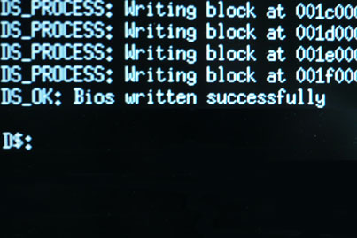
Once it's finished, a quick confirmation message appears and then it returns to the menu screen. You can restart your console now, the switch will still be in the position selecting the new flash chip, you should then see the 3D Animated Logo startup screen from the DreamCast Development Console.
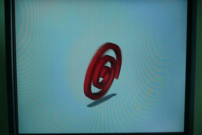
That's pretty impressive! The colour of the swirl depends on what region settings your console has. You can change it using the instructions here (you don't need to download the region changing disc though, it's included in the DreamShell disc). Remember to disconnect the link wire after you change your consoles region/swirl colour.
You can either mount the switch in the case allowing you to select the BIOS, or you can hide the switch in the console somewhere (probably best to wrap it in insulation tape and stick it somewhere to stop it rattling around), or you can remove the switch and hardwire it to always boot from the new BIOS.
You can see I've removed the switch and soldered a wire from the same point on D501, to the resistor which is going to leg 12 of the new Flash chip. The third and fourth photos above shows the slightly tidier install I've done following my own guide.
Here's a copy of the diagram from DC-Swat, I've added a small bit of extra info which helped me solder it up properly.
Scrap that diagram, DarthCloud has done some lovely new ones! (backup here and here should that forum go offline)
All of the info can be found on ASSEMblergames Forums. I've picked out some of the most relevant posts below that I used to perform this mod.
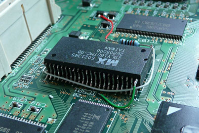
I recently bought some pre-flashed chips from Bad_Ad84 and removed the old chip from the motherboard to fit the new one (read this on how I remove the old one and solder the new one). This is the VA0 motherboard that you need to lift wire Legs 1 and 23 to leg 1 of nearby IC302. Leg 44 still needs wiring to leg 7 of IC502 (or, at least, a point that it's connected to).
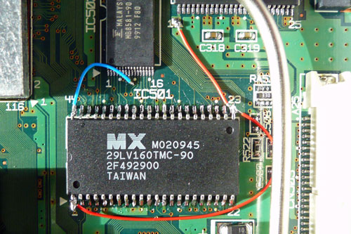
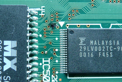
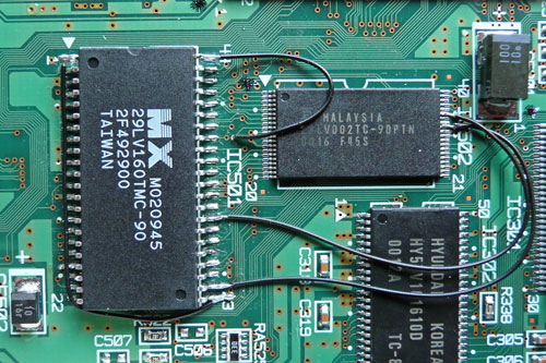
This one is a more common VA1 motherboard, still need to lift leg 44 and solder it to the necessary leg 9 of IC502 (well, the point shown in the photos is a lot easier to solder onto), and you need to lift leg 1 and solder it to leg 23. Ignore the other wires in this photo, this was a repair that I had done for someone.
Disc Image with Link83's modified BIOS
(hopefully not needed now)
Booting the Disc
